Ace Weld: more power to welding electronics
By Edit Team | August 16, 2018 9:35 am SHARE
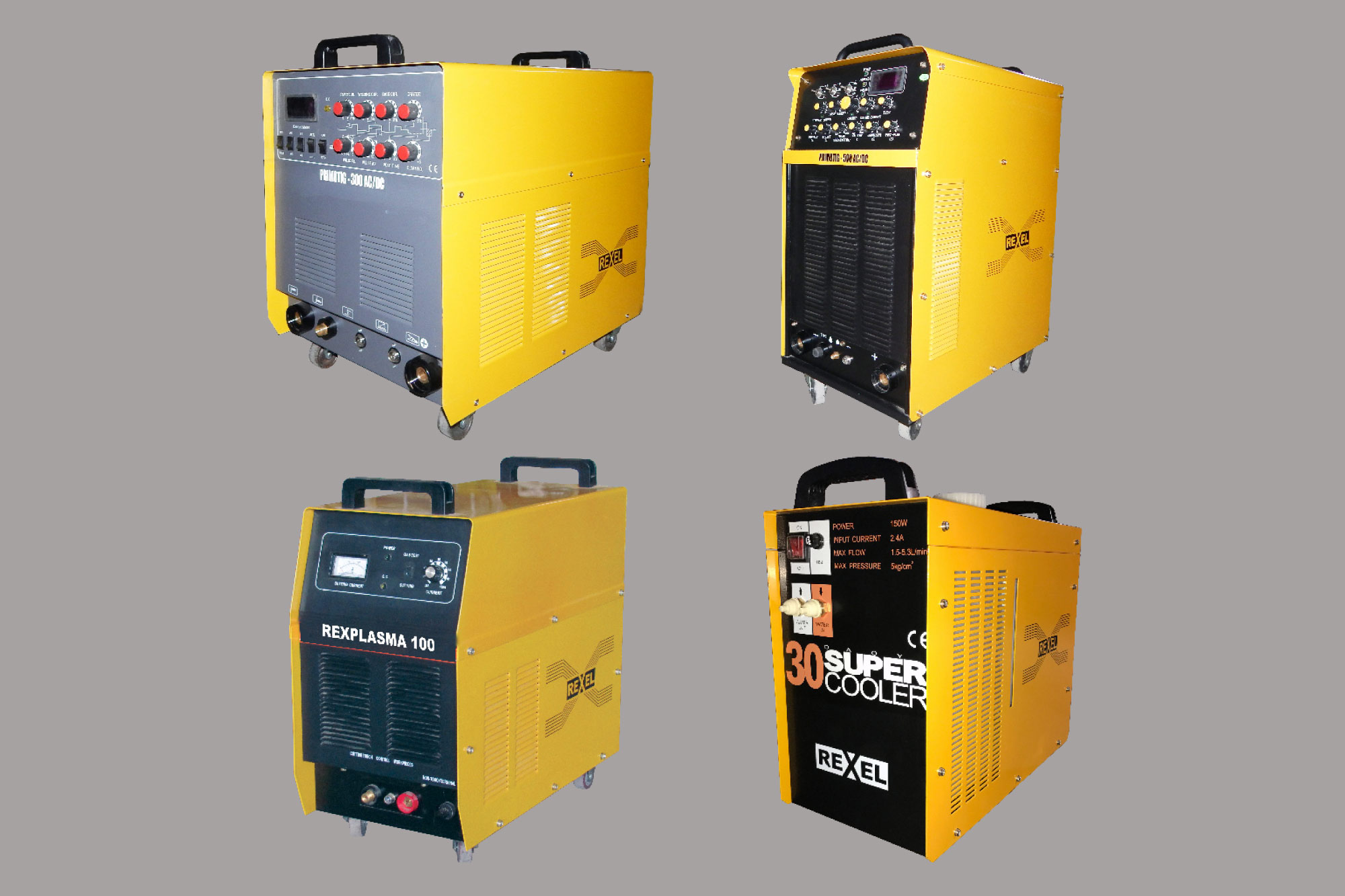
Power electronics is rapidly developing towards controlling power delivered to load very efficiently and precisely and also to save energy. The prime input energy to most of the work is in the form of electricity. In industrial environment, it is three-phase electrical energy.
This input power is available with different fault current levels depending on the installation of distribution transformers and having output impedance. So, while designing the product, Ace Weld Engineers has to consider input supply voltage, its frequency, allowable variation in voltage, its KVA capacity and distortion in supply wave form.
There is increasing demand for welding machines which will offer main application with desired characteristics along with features like easy to operate, welder-friendly, having better efficiency, compact in size, easy to transport and reliable. It is also required to have interfacing facility for control signal, sensor outputs, actuating commands, for semiautomatic and automatic operation of machine. With this, the entire welding system should be economically priced in a competitive market. Inverter power sources are becoming more popular in the market owing to their many advantages. Moreover, they are more reliable and maintainable. Their prices are now within reach of fabricators and fabrication workshops.
This has created the need to make use of electronics control circuit along with various types of power devices to meet increasing and moving needs of users in the market.
What is power electronics?
Power electronics is the branch of electronics where various power devices like power transistors, SCRS TRIACS, power MOSFETS, IGBTS are used to control power delivered to load through proper control of their conducting and non-conducting state by electronics controllers.
To achieve this, the company needs to conduct care full study of load to which power is being delivered. The load could be linear, non-linear or capacitive. In welding, the processes and their arc characteristics needs to be known thoroughly to get very good quality of welding.
In all welding processes, open circuit voltage and welding current is important to meet process requirements. Especially in SMAW process, open circuit voltage is required to initiate the arc smoothly. All welding processes basically work on short circuit principle. So, power device selection is very important. Welding current should increase gradually till the electrode or wire is fused. This fusing short circuit current and rate of rise of current decides the quality of weld bead. Higher current with sudden rise will result into spatter and arc will be violent. Power source should have current capacity to meet process requirements. However, passive component such as inductance and transformer impedance limits the rate of rise current and short circuit current. Electrical specification of power devices and their significance should be studied in order to suit the application. All this coordination of impedances and time is essential to get good quality of welding. The company has to ensure that power devices are operating within their specified limits given by manufacturers.
While selecting, it is necessary to decide output power and short circuit current rating to be handled by power devices.
Power sources available in the markets are classified as transformer with passive components, rectifier with diodes, rectifiers with SCR, inverters with power MOSFET, inverters with IGBT, inverters with power transistors.
Electronics controller
Electronics controller decides type of output characteristic of welding voltage and welding current. The relation between current and voltage is achieved by closed loop system through electronic controller. It can be either constant current or constant voltage characteristic. Both dynamic and static characteristics are important for welding performance. The sensors used to measure actual current in case of cc power source are DC current transformer, AC current transformer or shunt. The stability of current depends on stability and accuracy of sensors. PCB layout also plays vital role in giving stable and desired performance. Digital signal currents and analogue signal currents should be routed separately to reduce interference. Return path for these signal currents also to be carefully arranged for optimum performance of controller. This will contribute to reliability of controllers.
As we are using semiconductor power devices such as SCR, IGBT and power MOSFET, the circuits need to be circuited to protect these devices against abnormal conditions and disturbances. Today, there is more and more electronics in welding machine and all electronic components are sensitive to supply disturbances, environmental temperature, self-generated heat and dirt.
Error amplifier
From practical experience, it is observed that operational amplifier for industrial application with high input impedance and high gain is selected as error amplifier. It is used in negative feedback mode. The function of error amplifier is to compare set value with actual value and produce amplified error as control signal. It makes the error zero by giving control signal for PWM or to adjust conduction angle of SCR. This control signal produces the desired output. Because of high gain of error amplifier, the difference between set value and actual value is minimum and results in good regulation.
Advantages include – user friendly; step less adjustment of welding parameters; parameters can be set from remote place; in case of Inverter power source, compact and less weight; ease of transportation; invertor’s machine draws less supply current and consumes less power as compared to conventional machines resulting in saving, controllers to suit either cc or cv characteristics (selection of smaw or gmaw process), analogue setting or digital setting of parameters, power source can be interface for automation.
In recent development of welding power source, Insulated Gate Bipolar Transistor (IGBT) is used as the main power device. It is used to switch DC link voltage across primary of high-frequency transformer. The power cable connection from DC link capacitors to IGBT should be routed properly to pass primary current separately to both IGBT. The operating frequency for IGBT inverter power source is in the range of 16 to 20 KHz. The company has to ensure gate driving PWM signals get connected to IGBT with the shortest possible length of wires. Gate should be protected against surges and transients.
In lower current, power sources in the range of 200 to 250 amp operating on single phase supply smaller capacity IGBT or power MOSFETS are used. Power MOSFETS can be operated at higher frequency at 40 KHz or more.
SCRs works on mains frequency which is 50/60 Hz. Output current or voltage is controlled by phase angle control. Electronic control regulates either welding current or voltage. Devices are connected on secondary side of main transformer. SCRs can be used in different rectifier configurations.
Authored by:
R.K.Patwardhan
Ace Weld Engineers
Email: aceweld2008@rediffmail.com
Cookie Consent
We use cookies to personalize your experience. By continuing to visit this website you agree to our Terms & Conditions, Privacy Policy and Cookie Policy.





-20240213125207.png)


