Corrosion problems and its control in underground pipeline
By Edit Team | July 13, 2020 6:07 am SHARE
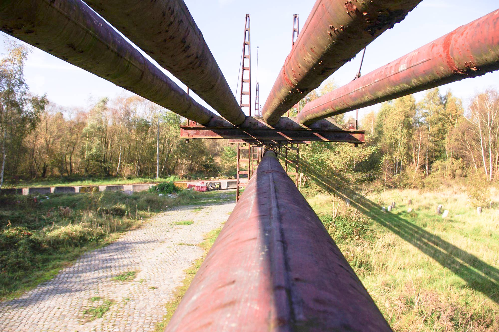
Corrosion is a serious problem. Internal corrosion of pipelines depends upon the type of fluid, while external corrosion is dependent upon the climatic conditions.
Underground pipelines are one of the safest means of transportation of crude oil, gas and water. However, the biggest challenge to make them safe, especially for flammable fluids such as crude, gas and some hydrocarbons from fire accidents. Earth acts as the first defense of safety. Corrosion is a serious problem. Internal corrosion of pipelines depends upon the type of fluid, while external corrosion is dependent upon the climatic conditions. For underground pipelines, internal corrosion is not a very serious problem and is usually tackled by injection of inhibitors, however, external corrosion is a real threat that is controlled by a combination of coatings and cathodic protection.
Introduction
Pipelines control to a greater extent our daily life cycle. The very basic requirement of life, the water, that reaches our homes through pipelines, essential ingredients of our life such as petrol, diesel, and many other important hydrocarbons reach us through pipelines, natural gas, which is used in running several power plants, fertilizers plants, is transported through pipelines. Cooling water for condenser of a power plant requires a robust pipeline to transport sea water at very high volumes.
Sewage disposal from residential buildings and industrial plants is also carried out effectively using a very strong network of pipelines. Though, we cannot think of a system without a pipeline link to take care of essential requirements of our homes, industry, transportation systems such as ships, commercial vehicles also use complicated pipeline network to supply fuel, cooling water to run the engine. All piping systems have one common problem of corrosion. This chapter would, however, restrict the discussion on the corrosion-related problems of the pipeline systems transporting crude, gas, hydrocarbons and water only. Most of these pipelines used for transportation of fluids are divided into two categories:
- Underground pipelines, carrying crude, gas and water
- Above-ground pipelines, carrying hydrocarbons within an industry’s boundaries, water, either for drinking or for fire-fighting applications
From the point of view of corrosion and its protection strategies, underground pipelines are very important and protection methods such as coatings, cathodic protection and use of chemical inhibitors, are usually employed. Above-ground pipelines, in fact, face even larger threat of corrosion due to changing climatic conditions, and pilferage from people and natural disasters such as thunderstorms, tree falling, building or structure collapse, but do not pose a security threat compared to the case of underground pipelines, which carry inflammable materials. In this paper, however, we will focus on underground pipelines.
Underground Cross Country pipelines (UCCP)
There is a huge network of underground pipelines across the globe. The UCCP lines are made to transport crude and gas which are inflammable and can catch fire if released due to some accidental leak or damage. That is why the first and prime safety factor considered for UCCP is the earth itself, which acts as the first defense to contain fire or release of the inflammable material to the environment. Usually, the pipelines are kept 6 feet below the earth level and nicely protected by gravel and mud to insulate them from the outside environment. Different countries have different lengths and capacities of these pipelines, spread across various land terrain varying in softness, hardness, sandy, rocky, or full of minerals or moisture. These terrains can be under-sea, river beds, brackish water etc. Thus the first step in laying underground pipelines is the selection of laying route as per right of way permissions from several agencies in that state or county.
There are more than 6,500 offshore oil and gas installations in some 53 countries around the world. More than 50 per cent of these installations are in the US Gulf of Mexico. The next five largest areas in descending order are Asia, Middle East, North Sea, West Africa coast, and South America. These six regions account for the majority of the existing offshore oil and gas installations. The installations are built for exploration (drilling) and production (including preparing water or gas for injection, processing oil or gas, cleaning produced water for disposal, and various accommodations).
India has more than 25,000 KM of UCCP, with more than 50 per cent transporting crude and gas and balance the refined product. These pipelines are spread over several states and passing through cities, villages, riverbeds, in various cities and villages and towns. Figures 1 and 2give a network of various pipelines for crude and gas respectively, spread across the country[1]. This does not include a network of compressed natural gas distribution lines, already working in many big cities such as Mumbai, Delhi, Ahmedabad, Baroda, Chennai and Bengaluru.

Fig 1: Network of Oil pipeline in India [1]

Fig 2: Network of gas pipeline in India [1]
Corrosion of UCCP
Though steel has excellent properties in terms of its strength, ease of fabrication as well as its low cost, it has one of the important drawback of getting corroded. Thus, steel needs corrosion protection wherever it is used. The corrosion protection of steel is a very important subject and methods like galvanization, coating by paints, use of inhibitor chemicals are the main methods of protection of steel.
It is easy to understand corrosion of steel when exposed to open environment, but the reason for the corrosion of pipelines when buried in earth appears to be un-understandable. The earth or terrain under which a pipeline is buried varies considerably from place to place. The soil under the earth can be soft mud, sand, rocky, soil with lots of minerals and moisture, brackish water or marshy land or a river bed. All of these create a different local environment which causes the corrosion of underground buried pipelines. Given below are several examples where buried pipelines corrode.
The corrosion occurs because of formation of differential corrosion cells on the pipelines due to the presence of soils with varying oxygen levels, steel pipes, exposed to a soil of varying compositions, such a sandy vs clay or soil of different moisture levels will also create anodic and cathodic areas resulting in corrosion steels pipelines having stressed areas ( welded areas) to unstressed areas [2].
Corrosion is one of the major causes of pipeline failure. Data from an American gas pipeline in 2011 showed that about 22 per cent failure of pipelines were due to corrosion alone, slightly less than the material failure, fig. 3 [3].

Fig 3: Causes of pipeline failure in 2011 [3]
Methods of Corrosion Protection of UCCP
Corrosion protection of pipeline is classified as internal and external corrosion. As per the schematic of a pipeline as shown in Fig. 4, the internal corrosion is due to the fluid flowing in the pipeline, crude or gas or water, while external corrosion is due to the soil corrosion as described in the penultimate section. Internal corrosion is usually not a serious problem unless the crude is sour( H2S level more than 500ppm) in nature. In the case of sweet crude or gas, the internal corrosion is usually taken care of by the addition of inhibitors into the pipelines. Sometimes, a 50 µm epoxy coating is applied to take care of the drag problems in the pipe. External corrosion problems are considered to be serious and require high class protective coatings, followed by additional protection from cathodic protection.

Fig. 4: Schematic of pipeline corrosion issues
Internal Corrosion in UCCP
Corrosion on the internal wall of a natural gas pipeline can occur when the pipe wall is exposed to water and contaminants in the gas, such as H2S, CO2, or chlorides. The nature and the extent of corro¬sion damage are the functions of the concentration of various corrosive constituents, such as CO2, H2S, water/moisture entrapment, pH, within the pipe as well as of the operating conditions of the pipeline [4]. For example, gas velocity and temperature in the pipeline play a significant role in determining the corrosion damage and its location. In other words, a particular gas composition may cause corrosion under some operating conditions but not others. Therefore, it would be difficult to develop a precise definition of the term “corrosive gas” that would be universally applicable under all operating conditions.
The main effect of CO2 is to dissolve in water and form carbonic acid which dissociates and changes pH, which in turn causes corrosion.
“H2O+CO2 → H2CO3”
“H2CO3 → H+ + HCO3-”
Usually, upto 40oC, a non-protective carbonate layer is formed but at temperatures higher than 40oC, upto 80-100oC, the carbonate layer formed is protective and hence the corrosion rate falls.The de Waard and Milliams model is to predict sweet corrosion [5]. They developed this model to investigate the corrosion of pipelines carrying wet natural gas containing CO¬2. The relationship between pH and Carbonic acid concentration is given below:
“pH(pCO2 = 1) = 4.17 ×10⁻³ T+371”
Subsequently, they derived a simple equation to predict corrosion in sweet system
“log Ccorr”=5.8-1710/T+ 0.671log〖(p”CO2″ )〗
Where Ccorris the corrosion rate, T is the temperature in oC, and pCO2 is the partial pressure of CO2.
At scale temperature Tscale, corrosion rate starts to decrease. It depends on the flow rate i.e. higher flow rates lead to higher scaling temperature
Tscale= 2400/(6.7+0.6log(fCO”2” ))
The situation changes drastically when H2S is also present with CO2. This is explained as per the model explained by Srinivasan model [6]. The effect of H2S depends on its partial pressure. At the partial pressure of H2S less than 0.01 psi, CO2 is the dominant corrosive species and the corrosion rate and surface layer formation are a function of FeCO3 concentration. When the partial pressure of H2S is higher than 0.01 psi and pCO2/pH2S is greater than 200, an iron carbonate layer can form depending upon the pH and temperature. However, when pCO2/pH2S is less than 200, an iron sulfide layer is formed preferentially.
Methods of combating Internal Corrosion
Usually, internal corrosion problems arise when crude or gas is sour in nature. For sour gas environments, usually, a corrosion-resistant coating is required. These internal coatings are usually epoxy based coatings and are applied by the internal spray of epoxy coatings. However, crude or gas when transported to refineries and storage tanks, sulphur and moisture are removed to make the fluid sweet, after which use of various inhibitors helps in combating internal corrosion of pipelines. The basic purpose of these inhibitors is creating a thin film of organic material on the inner steel pipe which prevents its direct reaction with the moisture or corrosive gases. Most of the inhibitors used for oil and gas applications are usually organic in nature, for example, acetylene, alcohols, quaternary ammonium salts, aldehydes, amines, etc. [7]. The effectiveness of inhibitors varies in static and flow conditions. Active inhibitors recommended for various flow conditions are long-chain amines, fatty amides, imidazolines, fatty acids, and their salts [8].
External corrosion problems
External corrosion of pipelines is due to a continuously varying environment of different kinds of soils, sand, marshy land, brackish water, riverbeds, and sea organisms and microorganisms, espe¬cially SRB. In addition, the corrosive environment of soils due to moisture, minerals, oxygen, chloride, etc., further enhances corrosion of the pipeline external surface. Coatings are a natural choices to create a barrier for the corrosive environment in soils. Over the years, there have been different coating materials and formulations used to protect pipelines. For example, in the 1940s and 1950s, coal tar, wax, and vinyl tape were used; in the 1960s, asphalts were used; and in the 1970s to the present day, several polymer-based insulating coatings are being used. Polyethylene (PE) tape and extruded PE jacket material also have been used from the early 1950s to the present day. Fusion-bond epoxy (FBE) was one of the most successful since the 1970s and is equally popular even today.
It is most important to note that the coatings alone are not a permanent solution for the corrosion protection of pipelines as the coatings deteriorate with time while interacting with the environment. Hence, to take care of this degradation in the underground pipelines, additional protection using cathodic protection is given. A total pipeline protection system thus includes consideration of steel quality, coating applica¬tion, surface condition and treatments, design of coating, and cathodic protection system.
Though, there are many types of coatings that have been applied on buried pipelines, the three main coatings, commonly used for pipelines are coal tar, FBE coating, and three-layer PE (3LPE) coatings. The coaltar coatings are now banned due to the release of carcinogenic vapors affecting the workers. The most acceptable coating today is plastic coatings especially 3LPE which consists of a primer fusion bond epoxy layer, followed by a thick Polyethylene layer. An intermediate tie layer is required to join the primer FBE (polar) and external PE (non-polar).
FBE Coatings
Out of various organic coatings, epoxies have the strongest resistance to oxygen, moisture, and chlorides, which are important constituents of soil. Further, they are highly insulating with very low conductivity and high dielectric resistance. That is why epoxies are the preferred choice where strong corrosion resistance is the main requirement. There are many ways by which the epoxy coat¬ings can be applied: brush, spray, using liquid epoxies, or electrostatically spraying the fine epoxy powder on a heated pipe, which immediately melts it and fuses instantly.
The coating has good cathodic disbondment resistance, hot water resistance, and good flexibility (5° of pipe diameter) at −50°C. FBE coatings are thermosetting compounds, which, once set, cannot be re-melted. The most important requirements of the coating are surface once set, cannot be re-melted. The most important requirements of the coating are surface cleanliness, proper heating, and sufficient cure. The first step is the blast cleaning of the pipe to Sa21/2, followed by heating the pipe uniformly using an induction furnace [9]. This is followed by electrostatic spraying of FBE powder, which immediately melts and fuses. The hot coated pipe is quenched immediately. The temperature at the pipe surface usually ranges from 180°C to 210°C. The coating thickness depends upon the pressure of the FBE powder, electrostatic voltage, and conveyor belt speed. A 350–500 μm coating is required from a pipe diameter of 8 to 36 in. A schematic of FBE production is shown in Fig.5.

Fig. 5 Schematic of Single-layer Fusion Bond Epoxy coating on the Pipeline.
Three Layer PE Coatings
One of the drawbacks of such a thin-coated pipe is its damage during transportation and handling. In the mid-1980s and in the beginning of the 1990s, two additional coating systems were discovered. The first was the 3LPE system and the other was the dual-layer FBE system. The purpose of both these systems was to enhance the damage resistance of the single-layer FBE coating, described above. In 3LPE, it was achieved by the application of an extruded PE coating of 1500 to 3000 μm over the FBE primer layer of 100–150 μm. Since it is not possible to directly coat a PE layer over an already-coated FBE layer, an intermediate adhesive coat of polyolefin is made, which adheres primer to the FBE layer through its polar functional groups and to PE by its hydrocarbon groups [10]. The temperatures required to coat an adhesive layer and PE layers are, respectively, 220°C and 238°C, and the two coatings must be applied within a small time interval of 13–25 s (depending upon the pipe surface temperature).
Dual FBE Coating
Another way of strengthening Single FBE coating is to make a dual FBE coating. In dual-layer FBE coating, an outer layer of FBE powder of different composition is applied over the primer layer [11,12]. The purpose of the inner layer is to have strong adhesion to the pipe, while the outer layer is expected to be very tough to have high impact resistance. 3M made a coating system where the outer layer achieves maximum toughness because of the cellular structure of the coating. The method of application is very similar to that of a single FBE coating, and coating can be carried out in a single booth, with some guns carrying inner-layer powders and others carrying outer-layer powders, placed in such a way that the outer powder sprays after the inner powder is sprayed and is still not gelled [13]. The coating of the inner layer is generally fixed at 250 μm, while the thickness of the outer layer varies with the diameter of the pipe, 250 μm for 8–22 in. pipe diameter and 350 μm for a pipe of diameter above 22 in.
Thus dual FBE which has adequate thickness as well as has strong durable properties along with resistance to external damage has also one of the best coating for cathodic protection.
Three-layer PE, though has much larger thickness has two very serious limitations. Its poor response to cathodic disbondment as PE is totally impermeable to moisture. That is why Cathodic protection in 3PLE works only when external PE is damaged. Secondly, it has shielding corrosion problem, where once the corrosion starts under the coating, it grows continuously with time till it becomes a catastrophe.
In addition to these three main coating systems, several other coatings are also applied on pipelines. For example, for high-temperature fluids, polypropylene coating instead is used of PE. Tape coatings or wrappers are other types of coatings that are used for protecting pipelines, however, these are used only for rehabilitation [14,15]. The application involves cleaning the surface with a wire brush, followed by the application of a primer and then inner wrap and finally outer wrap coating as shown in the schematic Fig. 10. In Germany, there are a few examples where cold-applied tapes are used for short-distance new pipelines. Visco-elastic coatings is a very recent coating introduced a few years ago by trade name STOPAQUE [16]. This coating also, though good for rehabilitation work has been recommended for use of fresh pipelines in the Netherlands.
Field Joint Coatings
The field joint coatings are the coatings that are used to join individual pipes, coated in the field, just before laying them in the ditch. Such coatings are also called girth weld coatings as these are applied on the weld joint between the two coatings [17]. Since welds are vulnerable areas, prone to be attacked by corrosive species, they need to be coated with special care to enhance their resistance to corrosion while at the same time maintaining their compatibility with the main pipeline coating.
Though, there are many coatings that can be applied at field joints, such as liquid epoxy, elastomeric polyurethane, cold-applied tapes, and viscoelastic coatings, the most common and acceptable field joint coating is the heat shrink sleeve coating. These are basically the rubberized coatings that, on application and after heating shrink, hold the pipe. The first step is full cleaning of the girth weld area, followed by application of a primer epoxy coat. This is followed by the application of heat sleeve which requires uniform heating to make an excellent uniform coating on the welded area.
Protection of pipelines by cathodic protection
As discussed above pipelines are coated from external side by various kinds of coatings, CTE, FBE, 3LPE etc. It is well known that coatings are not permanent. They deteriorate with time. Hence for UCCP, which is designed for 30 year design life, there must be an additional fool proof method to check the coating deterioration. This is usually done by cathodic protection. The basic idea of a cathodic protection system is to protect the pipe through the use of an electrical current. This basically means that the entire pipe becomes a cathode and the sacrificial anode corrodes. There is no outside power source necessary for this type of protection because the anode material, itself makes the current to flow naturally. The sacrificial anode will eventually become totally corroded and will need replacement as the pipeline structure ages. Because of this reason of frequent replacement of anodes periodically and also because a large number of costly anodes are required, this method is not used for UCCP. Rather, impressed current cathodic protection (ICCP) method is used for UCCP lines.
Impressed current pipeline cathodic protection (ICCP) systems are generally used in larger structures because the galvanic anodes are not capable of producing enough current to provide sufficient cathodic protection. The impressed current requires a DC power source. Usually, other power sources are used and converted to the necessary DC. A variety of materials may be used as anodes for the impressed current, such as ferro-silica, platinum or other noble metals or alloys. In this case, the electron flow is due to application of current and not because of dissolution of anodes. Thus, the anodes have a long life and there is no need to replace them
Pipeline cathodic protection can be applied to new pipelines, systems that have been around for a while that need additional protection, and even in hot spots where corrosion is becoming a problem. This means that the life of existing pipeline systems can be extended and problems avoided through the use of this technology. A thinner-walled pipe may be used if it has been sufficiently protected, which can save quite a bit of money in the production of the pipeline itself. Cathodic protection also acts as a monitoring system for the pipeline. Pipe to soil potential is one of the criteria for assuring the protection of a pipeline. If the psp is – 850 mV w.r.t Cu/CuSO4 reference electrode, then it is protected. If however, the psp is lower than -740 mV, it is considered that the pipe has some damage due to coating failure [18].
There are very simple thumb rules of total protection of pipeline by coating and cathodic protection. For a low cost coating, the current required is rather high, so cost of latter is more. For a costly coating, the current required is less and hence CP cost is less. This is shown schematically in Fig.11 And also current required by three main coatings are tabulated in Table.

Fig. 6 Total cost of Coating and cathodic protection vs cost of coating
Conclusion
Transportation of crude and gas is an important activity of the oil and gas industry. Because of the flammability of transporting fluid, the best method is transportation by underground pipelines. However, both internal and external corrosion threats are there which need to be properly taken care of by appropriate corrosion protection methods. While, the use of inhibitors is the most acceptable method of controlling internal corrosion of pipelines, the use of coating and cathodic protection is required for external corrosion protection. The most acceptable external coating today in the world is three-layer PE coating for new pipelines. The cathodic protection not only augments the corrosion protection by coatings but also helps in monitoring its health by giving constantly the psp potential values.
For more details, contact:
Prof. AS Khanna,
IIT Bombay (Retd.),
Chairman, SSPC India
Cookie Consent
We use cookies to personalize your experience. By continuing to visit this website you agree to our Terms & Conditions, Privacy Policy and Cookie Policy.







-20240213125207.png)


