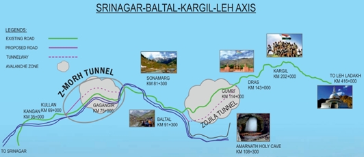
The Z-Morh and Zojila road tunnel projects, which are now under development, would offer a critical connection to Ladakh, overcoming the seasonal isolation imposed by hard winters and significant snowfall at the Zojila Pass.
Introduction
Connecting Ladakh with Kashmir poses significant challenges due to its fragile geology and harsh weather conditions, especially during the extreme winter months. Engineers face difficulties in developing and maintaining infrastructure in this challenging environment. Furthermore, the presence of two neighbouring countries with complex relations along the border adds to the existing complications.
A crucial aspect is ensuring timely logistics supply to the Indian Armed Forces deployed in the border areas. Overcoming the obstacles presented by the terrain and weather conditions is essential. The government and relevant authorities are working on strategies and solutions to address these challenges. They are focused on constructing robust roads, improving transportation networks, and implementing effective logistical planning. These efforts aim to ensure the smooth functioning of the Armed Forces and support their operations in the region.
Recognising these factors, the government actively supports significant infrastructural development in these mountainous regions. It has planned the construction of massive road tunnels to connect remote locations, providing all-weather connectivity to locals and the nation’s Armed Forces. These underground structures are designed to navigate the complex geology of the Himalayas.
Two prominent projects, the Z-Morh and Zojila Road Tunnel Projects, are currently under construction in these mountain ranges. Once completed, these projects will serve as lifelines for the people of Ladakh, who are cut off from the rest of India for approximately six months due to harsh winters and heavy snowfall at the Zojila Pass. Additionally, these projects will contribute to the socio-economic development of remote areas in the Union Territories and facilitate smoother Army supply and movement.

Briefs of Z-Morh and Zojila Projects
Z-Morh Project
Sonamarg, known as the Golden Meadow, is one of Kashmir’s popular tourist destinations alongside Srinagar, Gulmarg, and Pahalgam. While the other places are accessible year-round, Sonamarg faces a unique challenge due to heavy snowfall and avalanches on NH1, resulting in a four-month road closure. To ensure all-weather connectivity in the region, the Z-Morh Project was initiated.
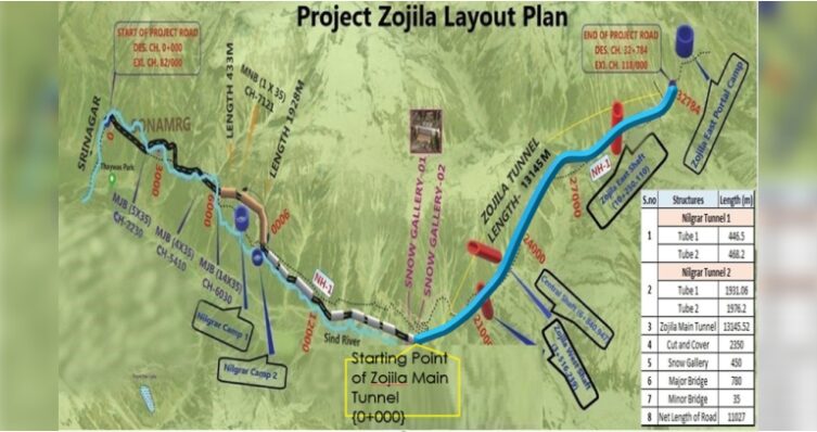
Located in the Ganderbal district of Jammu and Kashmir, the Z-Morh Project comprises a 6.412 km Main Tunnel, a parallel Escape Tunnel spanning 6.426 km, and approach roads totalling 5.568 km on both sides of the tunnel. With challenging structures like bridges and underpasses, the project aims to address the seasonal closure issue effectively.
By implementing the Z-Morh Project, Sonamarg’s road will remain accessible throughout the year, boosting tourism and contributing to the region’s economic growth. Visitors can enjoy Sonamarg’s beauty without worrying about the disruptions caused by snowfall and avalanches, making it a more attractive destination. Sonamarg, known as the Golden Meadow, is a popular tourist destination in Kashmir, along with Srinagar, Gulmarg, and Pahalgam. However, Sonamarg faces a unique challenge due to heavy snowfall and avalanches on NH-1, leading to a four-month road closure. To ensure all-weather connectivity in the region, the Z-Morh Project was launched.
Situated in Jammu and Kashmir’s Ganderbal district, the Z-Morh Project includes a 6.412 km Main Tunnel, a parallel Escape Tunnel spanning 6.426 km, and approach roads totalling 5.568 km on both sides. This ambitious project involves constructing challenging structures like bridges and underpasses to address the issue of seasonal road closures effectively.
Implementing the Z-Morh Project will provide year-round access to Sonamarg, boosting tourism and contributing to the region’s economic growth. Visitors will be able to enjoy the scenic beauty of Sonamarg without concerns about disruptions caused by snowfall and avalanches, making it an even more appealing destination. Continent-continent collisions give rise to mountain belts, the most prominent and distinctive geological features on Earth’s surface. Examples of such collisions include the Rockies and the Appalachian belt in North America, the Andes in South America, the Ural Mountains in central Eurasia, the Alps of Europe, and the Himalayas in Asia. Among these, the Himalayas represent our planet’s most recent and remarkable continent-continent collisional belt. The Himalayan orogeny results from the collision between the Indian and Eurasian plates, serving as a living testament to the ongoing mountain-building process. This collision has led to the formation of the world’s highest mountain range and plateau, making the Himalayas an awe-inspiring and dynamic geological feature.
Tunnelling through the fragile rock masses of the Himalayas presents numerous challenges to planners and engineers. These projects often encounter various tunnelling issues such as fault/thrust/ shear zones, unstable ground conditions, heaving, squeezing and swelling of rocks, rock bursting, groundwater inflow, high temperatures, and gas presence. Despite the unwelcoming conditions, these challenges provide valuable lessons for future endeavours.
Geological challenges in tunnelling in the Himalayas
Mountain belts, which are created by continent-continent collisions, represent the most dominant and unique geologic features on the surface of the Earth. Some of the best examples of such continent-continent collisions that lead to orogenesis are the Rockies and the Appalachian belt in North America, the Andes in South America, the Ural Mountains in central Eurasia, the Alps of Europe, and the Himalayas in Asia. The Himalayan orogeny is the youngest and most impressive of all the continent-continent collisional belts on Earth. The Himalayan Mountain Ranges are the product of the collision between the Indian and Eurasian plates and are a living example of a collision mountain belt as the process of mountain building is still active, forming the highest range and plateau in the world.
Tunnelling through the weak, fragile, jointed rock masses of the Himalayas throws many surprises to planners and engineers. Almost in all the tunnelling projects of the Himalayas some or other type of tunnelling problems have been encountered and are still being faced; like Fault/thrust/shear zones, running ground conditions, heaving, squeezing and swelling, rock bursting, groundwater inflow, hot temperature conditions and gases in rock, wedge/block failures, etc. Though it is a non-welcoming situation, still it gives lessons to learn.
Technologies
During the construction period
The tunnelling method used for Z-Morh and Zojila Tunnels is the New Austrian Tunnelling Method (NATM). As the name suggests, the method was first used in Austria (Salzburg) by Mr. Rabcewicz in 1962, and it gained worldwide recognition in 1964. In India, NATM is mostly used while tunnelling in the Himalayas.
NATM is a philosophy that involves designing a support system as you monitor the tunnel sections after excavation. The main principle of NATM is preventing the disintegration of rock mass, thus keeping its strength, and using rock mass as far as possible to take additional stresses resulting from excavation, which means that deformations should not be completely supported by supports immediately after installation.
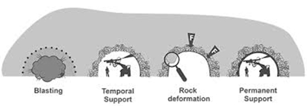
The process of NATM involves a cycle of the following steps:
- Survey and profile marking
- Drilling
- Charging
- Blasting
- Defuming
- Muck Removal
- Scaling
- Shotcreting (1st layer)
- Monitoring
- Support system (Wire mesh, lattice girder, rock bolts).
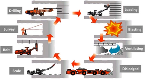
Excavation
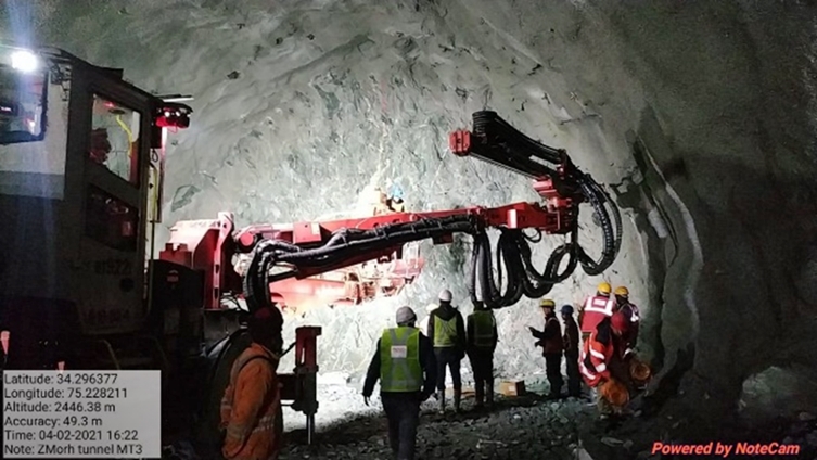
The drill and blast method is usually preferred for excavation in hard rocks, whereas for soft rocks, excavation is done through breaking. Before the blasting, the profile is marked using a Total Station. All the coordinates of the alignment are first fed to the Total Station. After the profile marking, when blasting is used, excavation is carried out in two parts: Heading and Benching. The heading is the top 65-70% of the tunnel section, whereas the remaining is the benching. Such a method is adopted considering the accessibility of the booms on the boomer machine. In Z-Morh and Zojila tunnels, excavation was done through blasting using an industrial-grade explosive, ANFO (Ammonium Nitrate + Fuel Oil). ANFO usually detonates through electronic detonators (EDs). Sequential blasting is used for the effective creation of free surfaces so that blasting is done up to the required length and desired fragmentation of rocks. The process of blasting is highlighted in the following figures:
- Drilling: Usually, drilling in the tunnel is carried out using a boomer. The length of holes is kept around 3-3.5 m, which indicates that in a single blast, around 3 m of excavation pull is achieved.
- Charging: The explosive used for the tunnel blasting is an industrial grade, commonly known as ANFO (Ammonium Nitrate + Fuel Oil). After the holes are drilled, the explosive is charged inside the hole. When the trigger is pressed, a current is generated in the ED, which initiates a spark, and the blast takes place.
In addition to the above, for effective blasting and to get the desired fragmentation of rocks, different blasting patterns are used such as wedge-cut, burn-cut, ring configuration, etc. In Z-Morh and Zojila Tunnels, a wedge-cut blasting pattern is used.
The numbers in both pictures indicate the sequence of blasting.
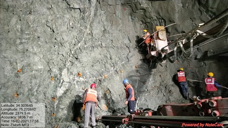
Installation of support system
The primary support in the tunnel after excavation is decided based on the quality of the rock mass which is usually decided by various rock mass classification methods. Some of the classifications used generally to design the rock support systems are:
- Terzaghi’s rock mass classification or rock load classification method.
- Stand-up time classification.
- Rock Quality Designation (RQD).
- Rock Structure Rating (RSR).
- Rock Mass Rating (RMR).
- Q-system.
- CSIR classification of the jointed rock mass.
In the Indian context, for the tunnels in the Himalayan region, usually, two main classifications are preferred by the design consultants, which are the RMR method and Q-value. RMR is a rating for the rock mass which is usually decided based on the six different parameters, involving rock mass strength, joint conditions, presence of water, etc., whereas the Q-system is a classification system for rock masses concerning the stability of underground openings. Based on the estimation of six rock mass parameters, a Q-value for a rock mass can be calculated. This value describes the rock mass quality.
For Z-Morh and Zojila Tunnels, the support systems are decided based on the RMR and Q-value systems of rock mass classifications. The primary support systems involve layers of shotcrete, rock bolts, wire mesh, foreboding, umbrella pipe roofing, and rock bolts/anchors, which are applied to the rock mass based on the above-mentioned classification parameters. For the reference purpose, the summary of the rock support systems installed in the Z-Morh Tunnel is as per the following Table 1:
Table 1: Primary support system as per RMR and Q values
In the above manner, the support systems are installed in the tunnel to overcome the redistribution of stresses resulted due to the excavation. After the installation of the supports, the tunnel sections are regularly monitored for any deformation.
Deformation Monitoring of the Tunnels
Geotechnical Instrumentation and 3D monitoring have a vital role in evaluating the performance of the underground structure. The Natural ground or rock mass tends to deform and de-stress when subjected to excavation or another loading such as overburden above the tunnel. For calculating that deformation, stress, etc. Instrumentation and 3D monitoring are required. The long-term performance of an underground structure is monitored by installing structural instruments to predict and evaluate the safety of excavated opening. The instruments used for measuring different parameters are:
- Bi reflex targets/Prism targets: used to measure convergence and Deformation in the rock mass.
- Load cells: Used to measure load or stress in rock bolts or anchors.
- Strain gauge: Used to measure deformation or strain/load in LG or rib.
- Multi-point borehole extensometer (MPBX): Measures deformation inside rock mass.
- Shotcrete/Concrete pressure cell: Measures total increase in pressure due to redistribution of stresses in the rock mass after excavation.
- Inclinometer: Used to measure lateral movements.
The data of the monitoring and instrumentation are regularly analyzed to identify any excessive deformation. In addition to that, different limits are set commonly known as AAA limits and the deformation would be closely monitored so that the value does not exceed a particular limit. AAA stands for Alert, Action, and Alarm and particular measures required for controlling the deformation shall be adopted timely. Some of the monitoring instruments are shown in the figures below.
After the construction period
Before moving further, mentioning that both the Z-Morh and Zojila tunnels are currently under construction is pertinent. Hence, the information shared in the article is purely based on the designs of the proposed systems (such as ventilation systems, E&M, fire-fighting systems, and SCADA).
During the tunnel’s Operation and Maintenance (O&M) period, various systems will be installed in Z-Morh and Zojila Tunnels. The systems installed will be fully automated and will be controlled by the SCADA system. The different systems to be installed are:
The fire-fighting system in the Z-Morh Tunnel considers the region’s challenging environment. Given the heavy snowfall and sub-zero temperatures, water reservoirs for extinguishing fires are located inside the tunnel. To ensure safety, numerous heat sensors will be installed along the tunnel alignment to detect potential fire incidents promptly.
CCTV cameras will be strategically placed inside the tunnel and along the project, alignment to monitor daily activities and ensure effective surveillance.
For ventilation, a semi-transverse ventilation system is proposed for the Z-Morh Tunnel. This system involves introducing fresh air through the tunnel portals and extracting exhaust air through equally spaced smoke extraction dampers along the length of the tunnel. The extracted air will flow outside the tunnel via an overhead duct.
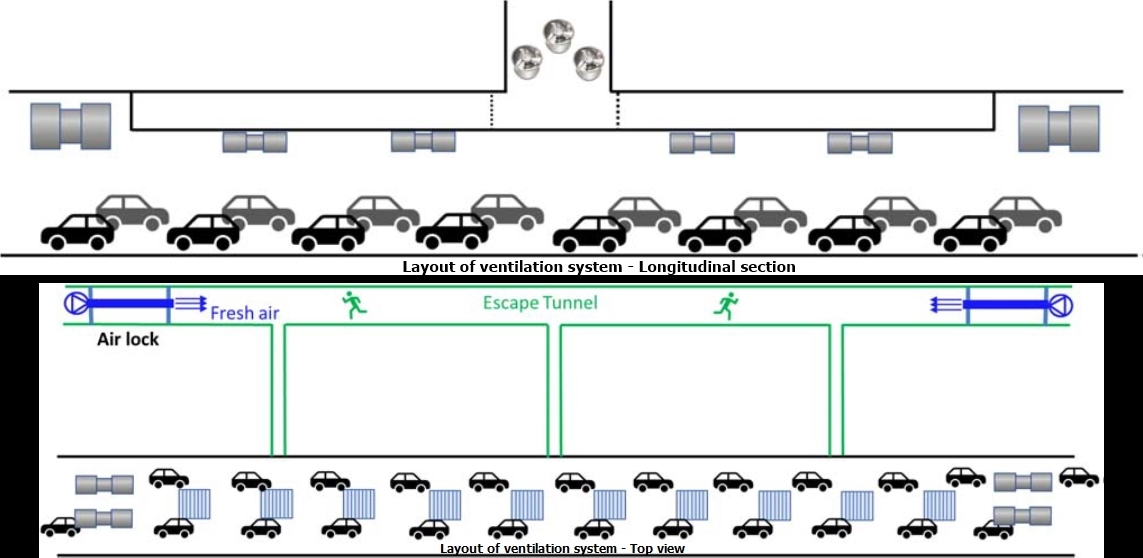
The ventilation system will utilise a combination of jet and axial flow fans, maintaining a maximum longitudinal airflow velocity of 10m/s. In a fire, the smoke extraction dampers will open fully in the fire area while other dampers will close, ensuring efficient smoke evacuation.
Conclusion
In conclusion, the Z-Morh and Zojila Tunnel projects on NH-01 aim to provide year-round connectivity to strategically important regions in Jammu & Kashmir and Ladakh. These projects will overcome challenges posed by heavy snowfall and avalanches, enabling safe and efficient transportation. Completing these projects will create local employment opportunities and boost the region’s tourism industry, contributing to economic growth.
The construction of Z-Morh and Zojila Tunnels is progressing rapidly, with Z-Morh expected to be completed by December 2023 and Zojila by December 2026. Advanced techniques are being employed to ensure worker and engineer safety, and strict adherence to quality control measures is maintained throughout the process. The tunnels will feature a modern Supervisory Control and Data Acquisition (SCADA) system with sophisticated instruments for a seamless commuting experience.
Furthermore, the authors emphasise the ongoing construction of several tunnels in the Himalayan Mountain ranges. The knowledge and experiences gained from these projects will be shared on a common platform to expedite decision-making and accelerate construction progress. Insights and expertise gained from operating and maintaining these civil engineering projects will be widely published, serving as a valuable resource for academic and practical purposes.
(This article is authored by Mr. Brijesh Ashokbhai Wala – Engineer, NHIDCL and Mr. V. K. Pandey – General Manager (Projects), NHIDCL.)
Cookie Consent
We use cookies to personalize your experience. By continuing to visit this website you agree to our Terms & Conditions, Privacy Policy and Cookie Policy.