
Scaffolding and formwork have a significant impact on construction projects and hence must be designed in detail. With its better designs, BIM proves to be a smarter solution for the purpose.
Scaffolding and formwork have a significant impact on construction projects and hence must be designed in detail. The safety of labour largely depends on the scaffoldings being used at a site. The system therefore should be designed keeping the safety of workers in mind. At the same time, it should also be easy to erect and should not be over designed as it can pinch the contractors or owners pockets.
The drafting of formwork systems for concrete structures is even more complex task than the design and selection of the formwork systems. The 2D Computer-Aided Design and Drafting (CADD) is the most commonly used tool for drafting along with add-ins for the 2D CADD software so as to reduce the amount of time and complexity in drafting the formwork systems.
“At times, more sophisticated 3D CADD is preferred, 2D technique suffers on the fact that it cannot incorporate the actual site characteristics such as the concrete shape, alignment of the formwork and construction sequence of the formwork, which are the detrimental factors in the formwork construction,” says Mudit Raniwala, CEO, Formworks, Technocraft Industries (I) Ltd.
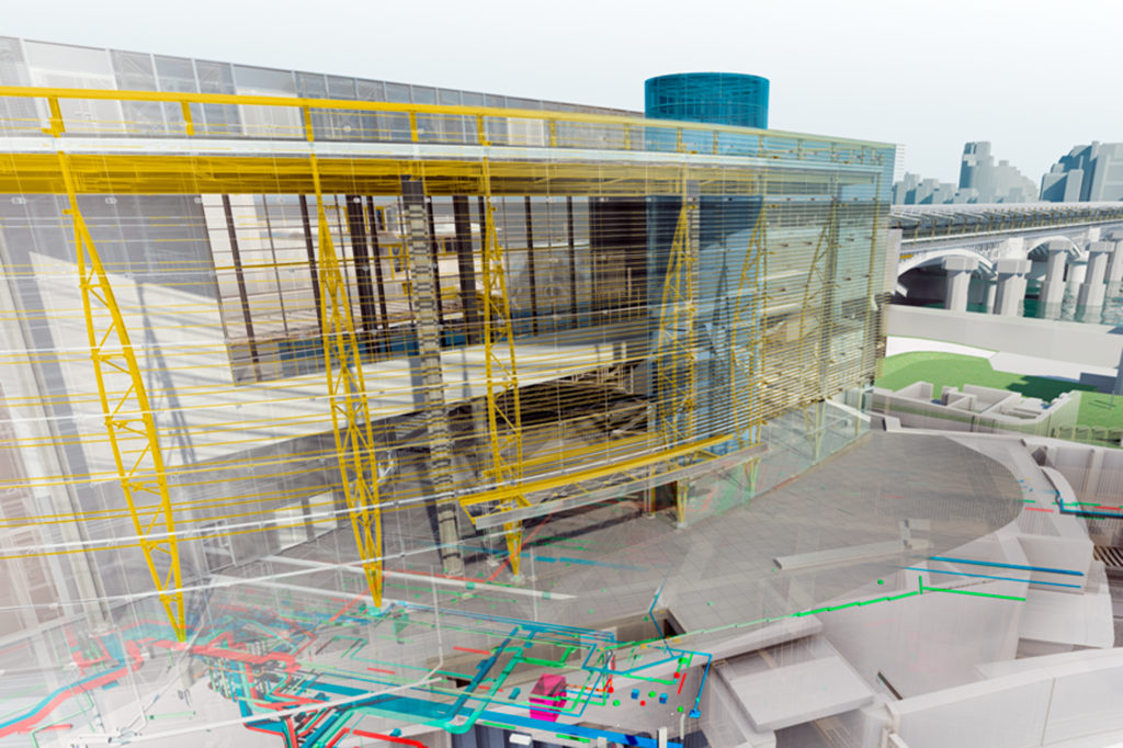
Using Building Information Modelling (BIM) proves to be a satisfying solution. BIM is simply a digital representation of physical and functional characteristics of a facility. It involves creating and using an intelligent 3D model to inform and communicate project decisions.
Why BIM?
BIM’s main feature that makes it desirable is its ability to automatically coordinate between drawings and details from a model eliminates errors and improves the accuracy.
“As the design and construction documentation are dynamically linked, the time needed to evaluate more alternatives, execute design changes, and produce construction documentation is reduced significantly,” points out Shekhar Banerjee, Marketing Director, Dhruva Scaffoldings.
Nirmalya Chatterjee, COO and Business Director, Tekla India Pvt. Ltd., says, “BIM helps to automate the formwork layout that saves the field crew time by eliminating the need to layout formwork for every wall in the building manually. The layout drawings are then given as hand-outs to the foreman to erect the formwork in the field.”
However, formwork layout has traditionally been a 2D process, field situations are often overlooked, inadequately accounted for, resulting in stripping and redoing of the formwork.
Considering their significant impact on construction projects, scaffolding as part of the temporary facilities category in construction must be thoroughly designed, planned, procured, and managed. The current practices in planning and managing scaffolding though is often manual and reactive, especially when a construction project is already underway.
“BIM technology can be used for modelling all the scaffold and formwork for whole buildings, offering a better level of planned occupational health and safety (OHS), edge protection and equipment fall protection to contractors prior to site commencement,” says Anand Sirohi, Head-Engineering, Natural Resources and Infrastructure (ENI), Autodesk India & SAARC. “It can be really helpful for the contractors as they can validate site planning for council, suggest most efficient site egresses and guide internal safety management processes. It also assists in quantity planning for scaffold and formwork requirements on both small and large projects.”
Uses of BIM
Use of BIM actually goes beyond the planning and design phase of the project, extending throughout the building life-cycle, supporting processes including cost management, construction management, project management and facility operation.
BIM helps a lot in formwork and scaffolding modelling and also automates many processes intelligently, some of which are:
• GA drawings/erection plans/layout drawings/3D views
• Create shop drawings
• Single parts drawings
• Formwork bill of materials
• Feed CNC files to workshop.
Current styles of design and planning
Formwork for concrete has to be designed to support all applied vertical and lateral loads until these loads can be carried by the concrete structure itself. In general, formwork system consists of sheathing to retain concrete and supporting members necessary to hold the sheathing firmly in place. Members which support sheathing directly are referred as studs in vertical formwork and joists in horizontal formwork.
Vertical loads include weight of reinforced concrete, weight of forms, and live loads imposed during construction due to material storage, workmen, and equipment. Lateral loads include lateral concrete pressure, wind loads, and impact loads due to starting and stopping of equipment.
A scaffolding system-loaded BIM model can be utilised in communication, billing of materials, scheduling simulation, and as a benchmark for accurate field installation and performance measurement.
However, it is useful to see what types of designs and planning are being implemented by current players in industry.
“A rule-based system that automatically plans scaffolding systems for pro-active management in BIM proves to be very helpful. A rule can be prepared based on the current practice of planning and installing scaffolding systems,” suggests Mr Sirohi. “The corresponding computational algorithms operating in a BIM environment will have the capability of automatically recognising geometric and non-geometric conditions in building models and produce a scaffolding system design which a practitioner can use in the field.”
Talking about the same rule-based system Mr Raniwala informs, “For our scaffolding products at Technocraft, we have developed a rule-based system that automatically plans scaffolding systems for management in BIM. However, the scope of this system is limited to traditional pipe and board scaffolding systems.
Having the bill of materials being generated through the systems helps us avoid the painstaking activity of drafting the entire layout before getting the material list.”
Technocraft Industries caters to the scaffolding requirements in construction as well as industrial or oil and gas sectors. It also makes designs and manufacture formwork systems for building and infrastructure projects.
Mr Chatterjee says, “By generating the formwork in 3D, complex issues and project specific issues are easily identified and assessed at an early stage which in turn avoids rework related to formwork erection. Formwork panels are prefabricated on site based on the information from the Tekla structures model.”
Mr Raniwala adds, “We use BIM extensively in design of our formwork systems too. The layout of concrete formwork systems is the most important factor to be considered in the formwork construction besides even the design and selection of the formwork systems.”
Earlier, the formwork components and its associated accessories were first drawn and then connected to form the finished formwork systems. However, this was time-consuming, thus later, the pre-drawn CAD elements known as Blocks/Templates were developed to draw the commonly used formwork systems. These blocks/templates are used as a separate or as add-ins for the 2D CADD software so as to reduce the amount of time in the drafting the formwork systems and its layout.
Mr Banerjee says, “Design, visualisation, simulation, and collaboration enabled by Autodesk BIM solutions provide greater clarity for all stakeholders across the project lifecycle. BIM makes it easier to achieve project and business goals.”
Technocraft uses 3D modelling extensively in design of the formwork to suit the shape in its infrastructure projects. The 3D CADD is efficient in providing an optimum solution but it is not impartible, means the changes made on it cannot be altered easily so as to coordinate with other construction elements involved in the project. Thus, there arises a need for an intriguing tool for enhancing the parametric change characteristics besides the perfect layout of the system.
“The BIM is one such technique that is adopted in our projects to overcome the shortcoming of the 3D CADD. This comprises of creating 3D BIM of the concrete structure like pier cap of flyovers and converting it into a wire-frame model and set as reference,” believes Mr Raniwala.
Bottom line
In summary, the most immediate benefits of BIM for formwork design are better designs and increased efficiency and productivity. Certainly, the way BIM is making its significance and importance felt, will open more doors for BIM applications in future.
—————————–
By generating the formwork in 3D, complex issues and project specific issues are easily identified and assessed at an early stage
Nirmalya Chatterjee, COO and Business Director, Tekla India
—————————-
—————————
BIM technology can be used for modelling all the scaffold and formwork for whole buildings, offering a better level of planned OHS, edge protection and equipment fall protection to contractors prior to site commencement
Anand Sirohi, Head-ENI,
Autodesk India & SAARC
—————————–
—————————-
Having the bill of materials being generated through the systems helps us avoid the painstaking activity of drafting the entire layout before getting the material list.
Mudit Raniwala, CEO,
Formworks, Technocraft Industries (I) Ltd.
——————————-
——————————
As the design and construction documentation are dynamically linked, the time needed to evaluate more alternatives, execute design changes, and produce construction documentation is reduced significantly
Shekhar Banerjee, Marketing Director,
Dhruva Scaffoldings
Cookie Consent
We use cookies to personalize your experience. By continuing to visit this website you agree to our Terms & Conditions, Privacy Policy and Cookie Policy.


Tex Hooper
July 8, 2022 at 4:46 am
I appreciate what you said about using formwork components. I need to get a scaffolding set up for my remodel. We want to build a second story.